


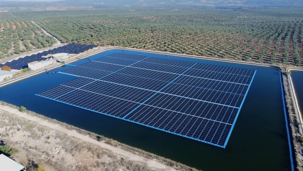

The safest and most reliable floating solar technology.
Proprietary and patented since 2008. Conceived and designed specifically for solar installations on water bodies.
A solution that integrates a three systems
Isifloating technology integrates three systems designed specifically for water, working together as a single engineering element.
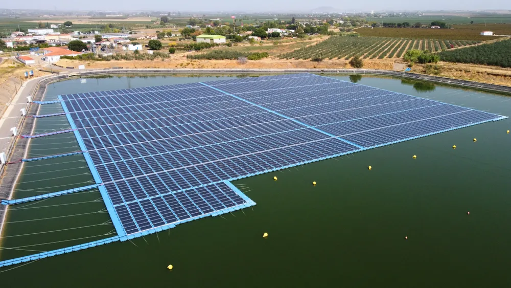
01
Floating structure
system
A floating solar plant is only as reliable as its foundation.
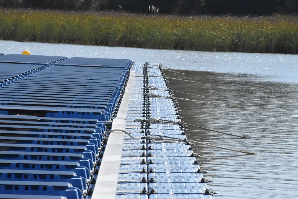
02
Anchoring and mooring system
The system that keeps the floating solar plant in place.

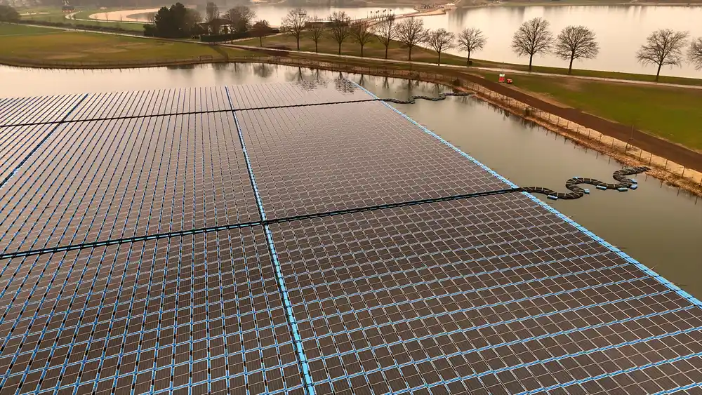
Floating solar technology designed for stable, durable and reliable performance
Developed in 2008 and proven in more than 100 projects, our technology is specifically designed to meet the challenge of turning water bodies into suitable and safe sites for solar plants.
2008
Year the technology was developed
+100
Projects in which it has been proven
Conceived to deliver a system that is:
Safer
Reliable
Easy to transport
Simple to install
Weather-resistant
Maintenance-efficient
Cost-competitive
Applied by experts in every project
Specialized engineers apply Isifloating technology to provide our clients and partners with robust, efficient, custom-designed floating systems based on:

Rigorous engineering
We design sound solutions that support informed, accurate decision-making, backed by expert technical judgment.
Continuous evolution
We apply the lessons learned since 2008 and advances in R&D&I to meet the present and future needs of floating solar.
Documentation
We support every floating solar system we design with clear, detailed documentation that enables informed decisions.
Adaptation
We tailor each project to its environment and objectives, including existing facilities for hybrid operation.
The Isifloating system: component by component
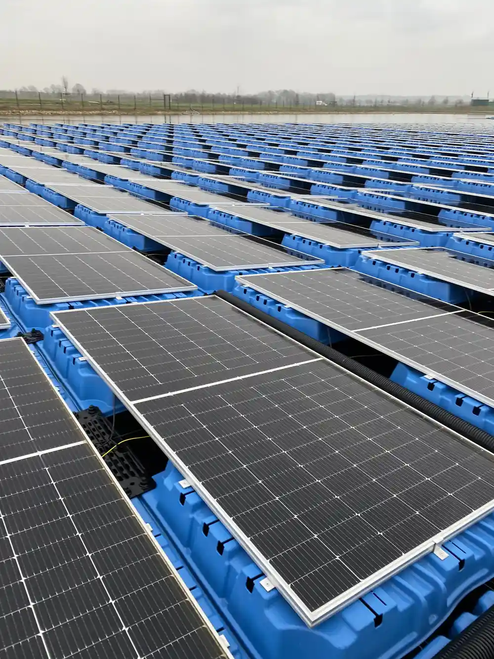
01 · Photovoltaic module support
Main float
Two interlocking floats support each solar module. They form a closed concave surface that distributes loads evenly. This design eliminates weak points and reduces structural stresses in the components and the module.
Material: virgin HDPE with UV and antioxidant additives.
5° tilt and closed back: 4.4 times lower wind load than 12° systems.
Injection molding: 100% consistent wall thickness, no residual stresses.
Dimensions optimized for logistics in standard containers.
Suitable for drinking water
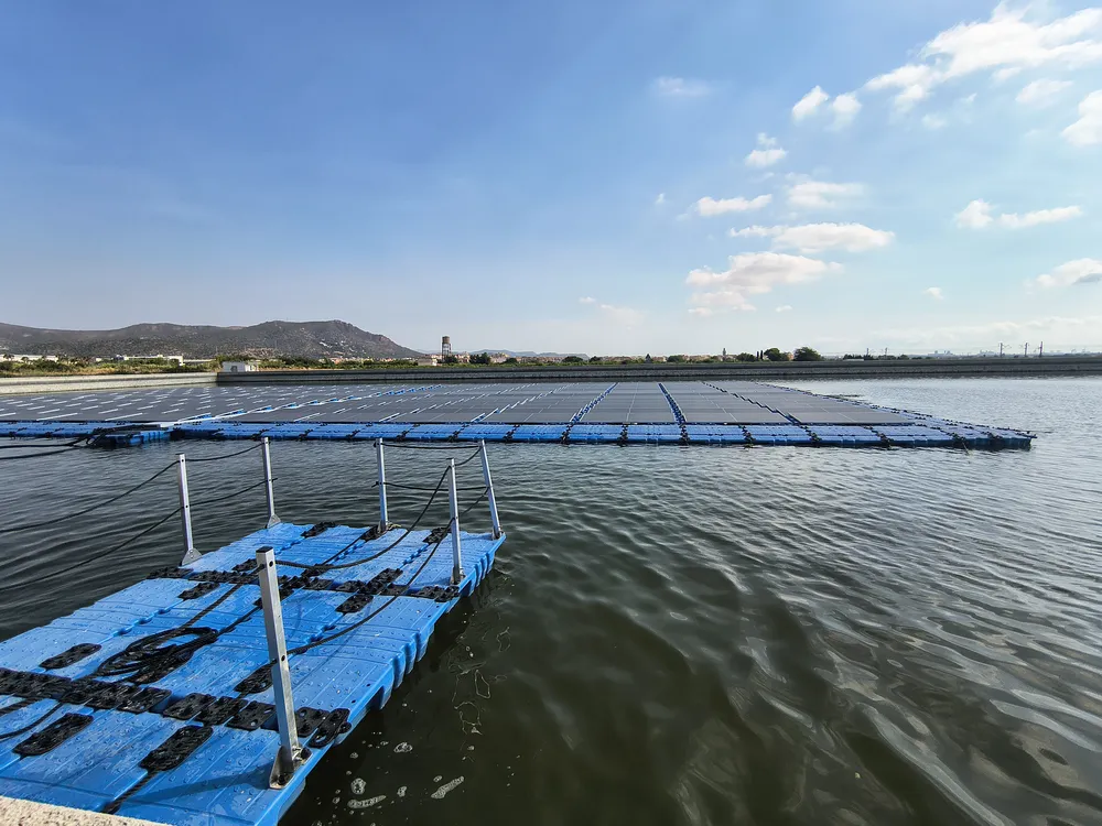
02 · Walkways and service corridors
Secondary float
They form the main walkways, allowing safe access on foot to every module. They allow integrating supports for cable trays, string inverters or combiner boxes, and other measuring equipment.
Material: virgin HDPE with UV and antioxidant additives, with anti-slip surface.
Buoyancy: 135Kg/m2.
Integrated cable routing.
Support for string inverters or combiner boxes.
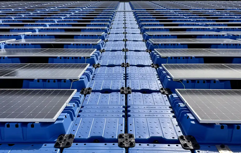
03 · Connectors and fasteners
Float connection system
The float connectors are flexible and semi-rigid, so they absorb and dissipate loads, preventing peak stresses from being transmitted directly to the structure and the floats.
Connectors: glass-fiber-reinforced PA6.
Bolts: corrosion-resistant, with no metal contact with the water.
Module fixing: 6063 T6 aluminum clamps.
Simple installation without specialized machinery.
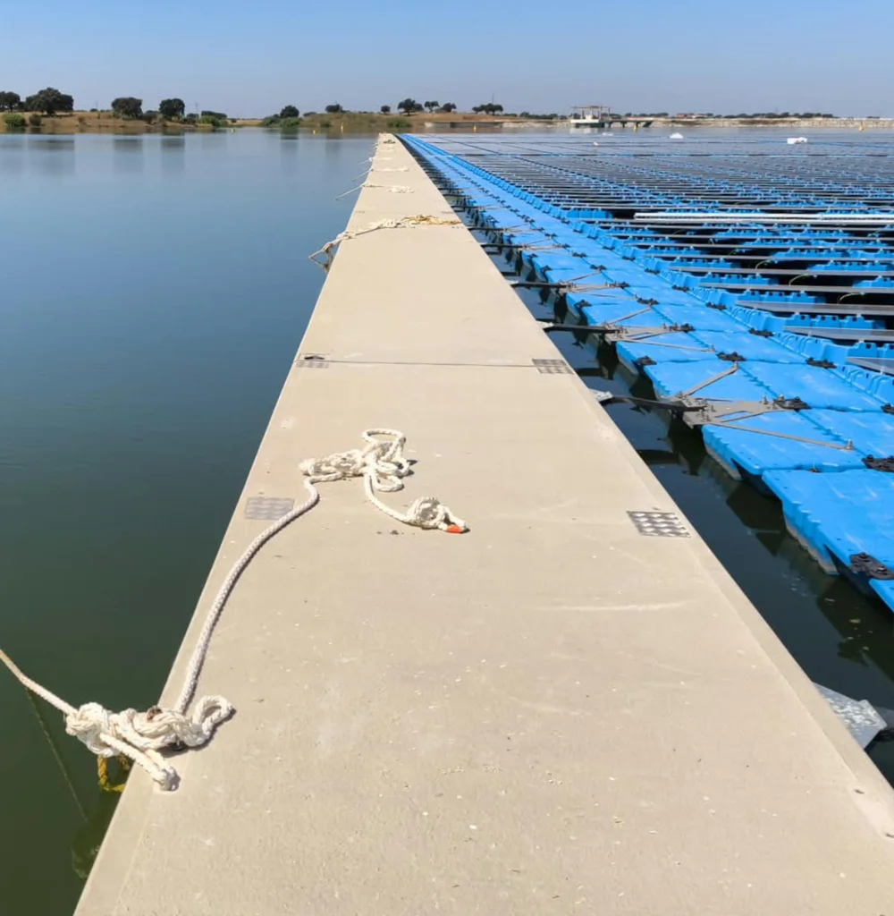
04 · Perimeter protection
Breakwaters
Physical barriers around the floating solar plant, configured as pontoons, that reduce component fatigue by acting as protection against:
Waves
They reduce wave height to lower the loads on the structure and the mooring lines.
Wind
They block it, reducing direct loads on the module rows along the outer perimeter.
Debris
They prevent floating objects from entering or impacting the plant, especially during floods.
Technical characteristics of the pontoons
Precast in Ultra High-Performance Concrete (UHPC).
Fiber-reinforced, self-compacting and high-strength.
Interior divided into cells filled with expanded polystyrene.
Breakwaters are required on large water bodies such as reservoirs and dams. We define their sizing in the project-specific engineering, based on the fetch of the water body, the prevailing wind direction and the plant orientation.
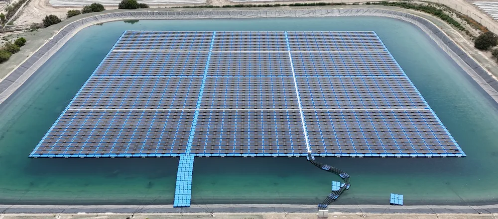
How it all fits together: the floating platform
Main floats, secondary floats, connectors and fasteners form a modular, scalable matrix adaptable to irregular water bodies. The platform is walkable and requires no cranes or heavy machinery for installation.
Our reference solution
Elastic mooring
Elastic mooring lines absorb peak loads and smooth the platform’s response. The Isigenere–Seaflex strategic alliance integrates both technologies into a single solution for each project.


SYSTEM 03
Electrical equipment support
Carrying energy safely over water.
The electrical infrastructure operates on a platform in constant motion. Our system integrates cable trays, string inverter/combiner box supports and transformer supports as an engineering assembly designed for the aquatic environment.
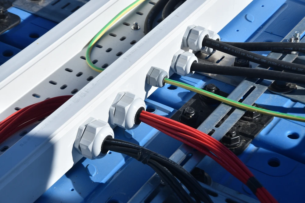
01
Cable trays and integrated cable routing
The secondary floats include supports for trays and conduits, allowing accessible, safe cable runs adapted to the platform’s movement.
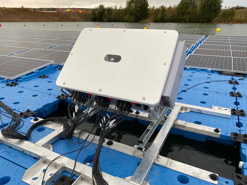
02
Inverter and combiner box supports
Dedicated positions for string inverters and combiner boxes, and metal elements that integrate this equipment into the floating platform.
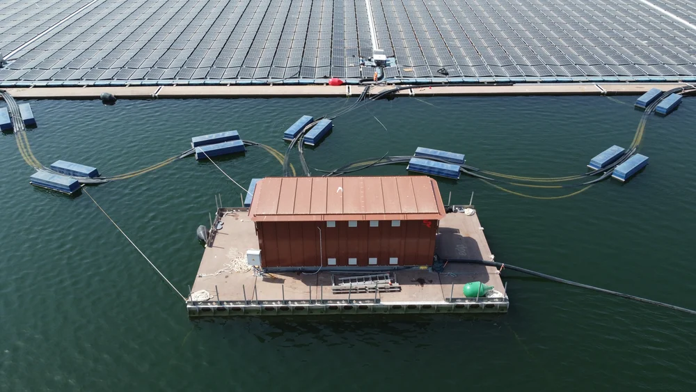
03
Transformer supports
Precast pontoons in Ultra High-Performance Concrete (UHPC), fiber-reinforced, self-compacting and high-strength.
04
From platform to shore: the electrical transition
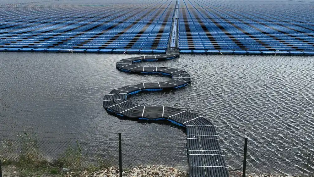
Buoys, flexible sections and conduits protect the cable on its route from the moving platform to the fixed infrastructure onshore.
Integrated electrical system design
The electrical support is designed as part of the project engineering, coordinated with the floating structure, the anchoring system and the electrical design of the client or EPC.
Documentation we deliver
Layout drawings
Cable routing drawing
Component specifications
Installation guides